PIC18 Microcontroller Robotics Project
Autonomous Object-Following Robot
Project Details
- Category: Robotics & Embedded Systems
- Language: C
- Date: May 2023
- Mark: 17.5 / 20 (A+)
- GitHub: Project Repository
- Project Report (in French)
- Project Beamer (in French)
This project, completed in collaboration with Cyril Herail, involved designing and implementing a robot system. We equipped the robot with sensors for distance measurement, battery monitoring, and added remote control functionality. Using the C language, we programmed the system to work with a PIC18 microcontroller, aiming for precise control, energy efficiency, and effective battery management. Throughout the project, we both gained valuable experience and skills in hardware design, coding, and problem-solving. Our collaboration resulted in a successful outcome for the robot project.
| Details of the Project Evaluation | |||
|---|---|---|---|
| Flowcharts | 16 / 20 | Protheus Simulation | 19 / 20 |
| Hardware Demonstation | 18 / 20 | Oral Presentation | 17 / 20 |
Introduction
| Work distribution | |
|---|---|
| Théo Gachet | Cyril Hérail |
Specifications and Goals
Our goal is to create a line-following robot: the robot detects an object or a person within a certain distance range (between 40 and 150 cm) and moves forward. If the detected object moves, the robot can follow it as long as their speeds are approximately equal.
Other specifications are provided. The microcontroller's oscillator frequency must be set to 8 MHz. The battery voltage must be averaged using four measurements and displayed in the UART, set at 9600 baud. Additionally, if the battery voltage drops below 10V, the Test LED should illuminate to alert the user, although the motors will continue to run.
The motor PWM must have a duty cycle below 50%. The remote control reception operates at 50 kHz, and only the central button is considered. Pressing the central button triggers a software interruption that starts or stops the robot, depending on its current state.
Calculation Details
ADC Period
We configure the ADC as follows: $$ADRES=\left(2^{10}-1\right)\times \frac{V_{AN2}-V_{SS}}{V_{DD}-V_{SS}}$$
We choose \( T_{AD}\) such that: $$T_{AD}=\frac{4}{F_{OSC}}=\frac{4}{8MHz}=0.5\mu s$$
According to the datasheet, we have: $$T_{ACQ} = T_{AMP} + T_{C} + T_{COFF}$$
Since \( T_{AMP}=2\mu s \) is always true (as we do not add an external conditioner), from the datasheet, we get: $$T_c=-(CHOLD)(R_{IC}+R_{SS}+R_{S})$$ where \( CHOLD=25pF, R_{IC}=1k\Omega, R_{SS}=2k\Omega \), and from the schematic, \( R_{S}=2.2k\Omega \).
We find \( T_{C}=0.991\mu s \) which is approximately one microsecond. At 25°C, \( T_{COFF}=0s \), and in the worst case (85°C), \( T_{COFF}=1.2\mu s \).
Thus, \( T_{ACQ}=4.2\mu s \) in the worst-case scenario. We can deduce: $$ ACQT2:ACQT1:ACQT0=\frac{T_{ACQ}}{T_{AD}}=8 $$ Hence: $$ACQT2=1 ; ACQT1=0 ; ACQT0=0$$
Battery Monitoring
We store the digital value obtained from the ADC conversion and average it with the last three measurements. The resulting value ranges between 0 and 255. We display this digital value (referred to as "valeur_batterie") in the UART. We also display the percentage of remaining battery, calculated using the formula: $$pourcentage=\frac{100\times valeur\_batterie}{255}$$PWM Generation
Timer 2 is used to generate the PWM signal for the motors. We want a PWM signal with a frequency of \(f=4000Hz\). First, we calculate the value of PR2: $$PR2=\frac{F_{OSC}}{4\times FPWM \times prescaler}-1$$ We want PR2 to be as large as possible but still less than 255. Thus, it follows: $$\frac{F_{OSC}}{4\times FPWM \times prescaler}-1\le 255$$ Since the prescaler can only have three possible values: 1, 4, or 16, in order for the condition to be satisfied, the prescaler must be 4 or 16. We choose 4 as it gives us the largest value of PR2. With this choice of prescaler, we obtain: $$PR2 = 124$$ Next, we calculate the values of CCPRxL, DCxB0, and DCxB1. Here, x can be either 0 or 1, differentiating the right motor from the left motor. Since the robot only moves straight forward without turning, these values are the same for both motors. When the robot is in motion, we set the duty cycle RC to 40\% as follows: $$CCPRxL:DCxB1:DCxB0=\frac{RC\times F_{OSC}}{100\times prescaler\times FPWM}$$
We have \( CCPRxL:DCxB1:DCxB0=200=0b0011001000 \). Hence, \( CCPRxL=200>>2=50=0b0000110010 \), DCxB1=0, and DCxB0=0.
When the robot is stationary, the duty cycle is zero, thus CCPRxL = 0, DCxB0 = 0, and DCxB1 = 0.
Timer0
The oscillator is set to 8MHz, providing a clock of \(F_{clock}=\frac{F_{OSC}}{4}=2 MHz\) to Timer0 input. We want a time base of 20ms, and the formula to calculate the period is as follows:
\[Period=(OV-reload)\times prescaler\times T_{clock}\]
We start by selecting the mode of Timer0 (8 bits or 16 bits), which will determine the overflow value. Here, we choose the 16-bit mode of Timer0, resulting in:
\[Overflow=2^{16} - 1=65 535\]
Next, we calculate the prescaler. By using zero reload, we obtain a prescaler of 4. Finally, we calculate the reload value:
\[reload=Overflow-\frac{T_{clock}\times period}{prescaler}=55 535=0xD8EF\]
In the code, we have TMROH = 0xD8 and TMR0L = 0xEF.
Simulations
Timer0 Period
The simulation of Timer0 appears to work correctly in Protheus. However, we wanted to verify that Timer0 strictly adheres to the specifications. While it may seem to function correctly, it is essential to ensure that errors are not overlooked. For example, we aimed for a time base of 20ms, but without thorough verification, it might have been 19ms or 21ms, which would be indistinguishable at first glance in Protheus. We slightly modified the code for the simulation in Protheus. We connected the oscilloscope to the Test LED voltage. The LED switches at each Timer0 interrupt, allowing us to measure the Timer0's time base and verify that it meets the specifications.
PWM Generation
Using the oscilloscope in Protheus, we verified that the PWM signal had the correct frequency, duty cycle (0 or 40%), and was the same for both motors. We particularly used the vitesse_moteur() function for this verification.
Battery Monitoring
For battery monitoring, we used the virtual terminal in Protheus to simulate the UART connection. We displayed the digital value and the corresponding voltage percentage. This way, we simulated the battery voltage using a constant voltage source. We checked if the digital value matched the input voltage. We performed tests with different voltage values. Verifying the monitoring required ensuring that the UART connection simulation was working to display the values. Other solutions were possible, such as using breakpoints, but this method was faster once the UART connection was programmed. Additionally, we also verified that the LED display worked correctly. We simply checked if the input voltage value corresponded to the expected LED display, as defined in the affichage_batterie() function.
Remote Control Reception
In the Protheus simulation, the remote control is replaced by a switch, so we cannot check the remote control's address. However, we can verify that the interruption works correctly on the microcontroller's corresponding pin. In the virtual terminal, we display "IT Telecommande" each time we detect an external INTOIF interruption, which happens when the central button is pressed. In the final code, we commented out the line of code that displays this message after verifying that it worked in the simulation.
IR Sensor Reading
In the simulation, the sensors are replaced by constant voltage sources, simulating the sensors' output. To verify that the ADC worked correctly, we displayed the digital values after converting the two sensors' outputs in the UART. We performed several tests with different voltage values. This also allowed us to verify that the algorithm worked correctly, i.e., the robot moved only when it was within a certain distance range. We verified this function first alone and then in interaction with other functions (vitesse_moteur(), surveillance_tele(), etc.). The code evolved gradually during this process. We also simulated certain corner cases, such as one sensor detecting an object at a relatively close distance while the other detects it at a much farther distance (as a reminder, our algorithm takes the average of the two values returned by the sensors).
Application
Explanation of Our Algorithm
At the beginning of the program, we initialize the oscillator to 8MHz, then the timers, and configure the inputs-outputs, PWM signal, I2C, UART, and interruptions. Before entering the while loop, we enable the interruptions. In the while loop, we test the flags sequentially.
The first flag triggers a call to the surveillance_batterie() function. In this function, we display the digital value of the battery voltage and the corresponding percentage in the UART. The 8 LEDs serve as a human-machine interface since the number of lit LEDs corresponds to the battery's percentage. When the battery is full, all the LEDs are on. It is worth noting that the digital value is an average of 4 measurements. For each new measurement, we remove the oldest value from memory and replace it with the most recent one.
The second flag triggers a call to the surveillance_capteur() function. We initiate an ADC conversion and obtain a measurement of the two sensors' output voltages. We average these two values, and if the robot variable is set to 1 and this value is within the correct distance range, we start the motors; otherwise, we stop them.
The robot variable is initialized to 0, meaning that the robot does not move until the remote control button is pressed. Each press of the remote control button toggles this variable (alternating between 0 and 1).
The third flag triggers a call to the surveillance_tele() function. We change the state of the robot variable.
Similarly, we use only the rising priority vector for our interruptions. In the high interrupt vector, we have several interruptions. The external interruption INT0IF is activated with each remote control press; we acknowledge the interruption and set the telecommande flag to 1. Then, we have the timer0 interruption, which we acknowledge and set the flag_capteurs_IR to 1. Every 10 times, we set the flag_batterie to 1. Since we need to acquire measurements of the sensors as frequently as possible, we do this every Timer0 interruption (every 20ms). Monitoring the battery voltage is essential but does not require such short time intervals. Therefore, we do it every 200ms (10x20ms) to avoid consuming CPU resources.
IR Sensor Reading
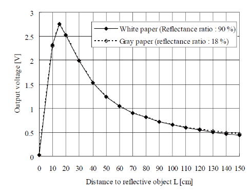
At the hardware level, we observe an analog voltage at the sensor's output. For an object placed at a fixed distance from the robot, this voltage remains constant. The datasheet of the sensor indicates a voltage of approximately 1.5V for an object placed at 40 cm, and we indeed find this voltage on the oscilloscope. At the software level, we display the corresponding numerical value for both sensors using the UART communication. As the sensors are slightly rotated, the numerical values are close but not completely identical.
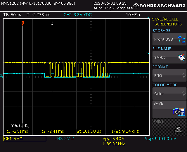
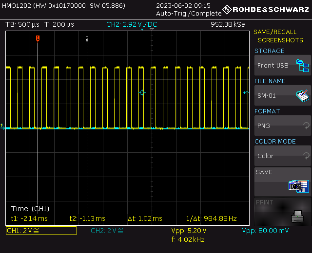
PWM Generation
When the motors are stationary, the PWM signal has a duty cycle of 0%. At this point, we observe some mV amplitude noise on probes J17 and J18. When the robot is in motion, we observe PWM signals for both the right and left motors. The PWM signal in both cases has a duty cycle of 40% and a frequency of 4000Hz. Below is a measurement of the PWM signal on the oscilloscope:
Conclusion
Differences from the Specifications
The specifications have been met. The only notable difference that still exists between our robot and the specifications concerns the PWM signal. The PWM frequency is 4000Hz instead of 1000Hz. The specifications specify a time base of 1 ms.
Possible Improvements
Several improvements could enhance the precision and efficiency of the system:
What We Have Learned
This project has been a very enriching learning experience for both of us, in terms of acquired knowledge and developed practical skills. The first phase of the robot project in Semester 5 allowed us to develop hands-on skills, such as learning soldering. Additionally, the second phase developed in Semester 6 enabled us to apply the knowledge and techniques learned to solve practical problems that we may encounter in our future professional careers. For example, I particularly enjoyed the coding part, finding embedded C learning very rewarding. On the other hand, Cyril enjoyed managing the board and searching for hardware bugs. This project has been an excellent opportunity to learn and progress in a different context from the more formal lecture-based courses.